With the rapid development of the global electric vehicle industry, various countries are speeding up the construction of electric vehicle charging piles. However, the EV charging connector types vary from country to country, which to a certain extent affects the convenience of EV charging.
At present, North America mainly uses SAE J1772 standard, Europe uses IEC 62196-1,2,3 standard, China is using standard GB/T 20234.1,2,3-2011, and Japan’s is using CHAdeMO standard. Figure 1 shows the types of EV charging connectors worldwide.
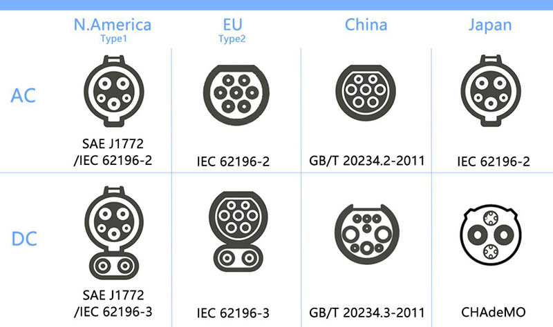
SAE J1772 Standard
SAE J1772 is a North American standard for electrical connectors for electric vehicles maintained by the SAE International and has the formal title “SAE Surface Vehicle Recommended Practice J1772, SAE Electric Vehicle Conductive Charge Coupler”.
SAE J1772 standard AC charging plug is shown in Figure 2.
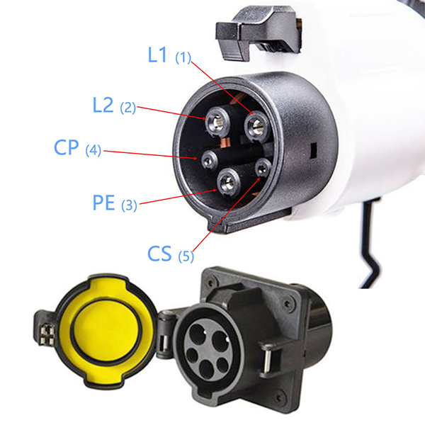
The function of each contact is shown in Table 1. for AC single-phase charging, its voltage and maximum current are shown in Table 2.
| Table 1: Function of each PIN according to SAE J1772 standard | ||
|---|---|---|
| PIN | Function | Primary AC and secondary AC |
| 1 | Mains 1 | Required |
| 2 | Mains 2 | Required |
| 3 | Ground | Required |
| 4 | Control pilot | Required |
| 5 | Connection switch | Required |
| Table 2: Primary AC and secondary AC | |||
|---|---|---|---|
| Charging Method | Supply Voltage (V) | Maximum Current (A) | Branch Circuit Breaker Rating (A) |
| Primary AC | 120V AC, Single-phase | 12A | 15A (minimum) |
| 120V AC, Single-phase | 16A | 20A | |
| Secondary AC | 208~240V, Single-phase | ≤80A | According to NEC 625 |
IEC 62196-1,2,3 Standard
Type 1
IEC 62196 is an international standard for set of electrical connectors and charging modes for electric vehicles and is maintained by the International Electrotechnical Commission (IEC).
The IEC 62196 standard type 1 charging connector contact definition is the same as the SAE J1772 standard AC charging interface, as shown in Figure 2.
| Table 3: Maximum voltage and current for each contact according to IEC 62196 Type 1 | ||
|---|---|---|
| PIN ③ | AC | Functions ① |
| 1 | 250V 32A ② | L1 (mains 1) |
| 2 | 250V 32A | L2 (mains 2) / N (neutral) |
| 3 | Rated for fault | PE (ground / earth) |
| 4 | 30V 2A | CP (Control pilot) |
| 5 | 30V 2A | CS (Connection switch) |
| ① For contacts 4 and 5, environmental conditions may demand larger conductor cross-sections. ② In the following countries, the branch circuit overcurrent protection is based upon 125% of the device rating: USA. ③ Positon number does not refer to the location and/or identification of the contact in the accessory. |
||
Type 2
The type 2 charging connector contact definition of the IEC 62196 standard is shown in Figure 3.
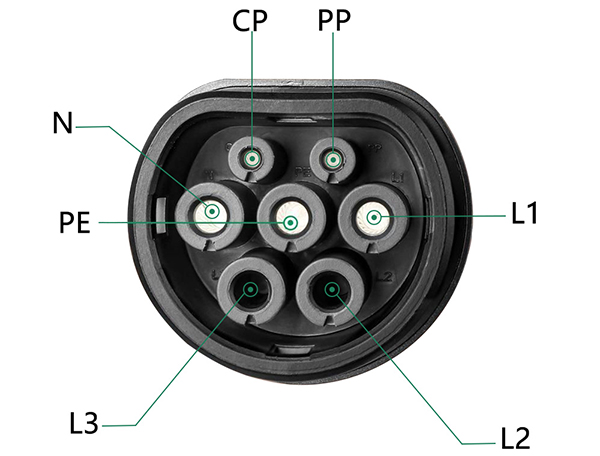
Charging power pins: line (L1), line (L2), line (L3), neutral(N), and protective earth (PE).
Signal pins: the control pilot (CP) and proximity pilot (PP).
The maximum voltage and current of the IEC 62196 standard charging connector in three-phase and single-phase power are shown in Table 3.
| Table 4: Maximum voltage and current for each PIN according to IEC 62196 in three-phase power and single-phase power | ||||||
|---|---|---|---|---|---|---|
| PIN ⑥ | Three phase | Single phase | Functions | |||
| Umax | Imax ① | Imax ① | ||||
| V a.c. | A | A | ||||
| Type 2 | Type 3 | Type 2 ② | Type 3 | |||
| 1 | 500 | 63 | 32 | 70 | 32 | L1 (mains 1) ② |
| 2 | 500 | 63 | 32 | – ③ | – ③ | L2 (mains 2) |
| 3 | 500 | 63 | 32 | – ③ | – ③ | L3 (mains 3) |
| 4 | 500 | 63 | 32 | 70 | 32 | N (neutral) ②③ |
| 5 | — | Rated for fault | PE (ground / earth) | |||
| 6 | 30 | 2 | CP (Control pilot) | |||
| 7 | 30 | 2 | PP (Proximity) ④ or CS (Connection switch) ④ |
|||
| ① In the following countries, the branch circuit overcurrent protection is based upon 125% of the device rating: USA. ② For single phase charging contacts 1 and 4 shall be used. ③ Unused contacts need not to be installed. Not provided for standard sheets 2-llla and 2-lllb. ④ Not provided for standard sheet 2-llla. ⑤ For single phase system supply phase to phase this contact can be used for L2 (mains 2). ⑥ Position number does not refer to the location and/or identification of the contact in the accessory. |
||||||
CHAdeMO Standard
CHAdeMO was formed by The Tokyo Electric Power Company, Nissan, Mitsubishi and Fuji Heavy Industries. Toyota later joined as its fifth executive member. Three of these companies have developed electric vehicles that use TEPCO‘s DC connector for quick charging.
The contact definition of the charging connector of the CHAdeMO standard can be seen in Table 5, while Figure 4 shows the timing circuit of the CHAdeMO.
| Table 5: Function of each PIN according to CHAdeMO Standard | |
|---|---|
| PIN | Functions |
| 1 | Ground |
| 2 | Charge sequence signal |
| 3 | Not connected |
| 4 | Charging enable |
| 5 | DC power |
| 6 | DC power |
| 7 | Connector proximity detection |
| 8 | CAN bus |
| 9 | CAN bus |
| 10 | Charge sequence signal |
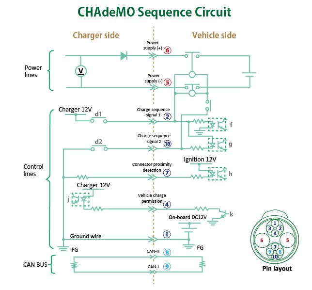
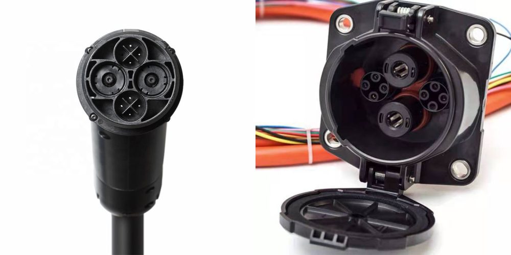
The CHAdeMO standard can output high voltage DC power up to 62.5kw. Figure 5 shows the CHAdeMO standard EV charging connectors.
GB/T 20234.1,2,3-2011 Standard
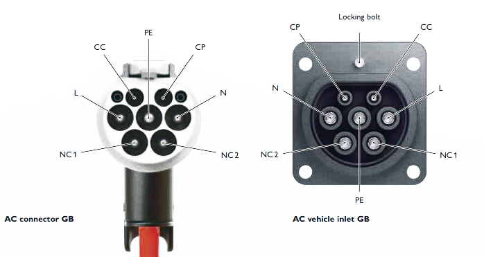
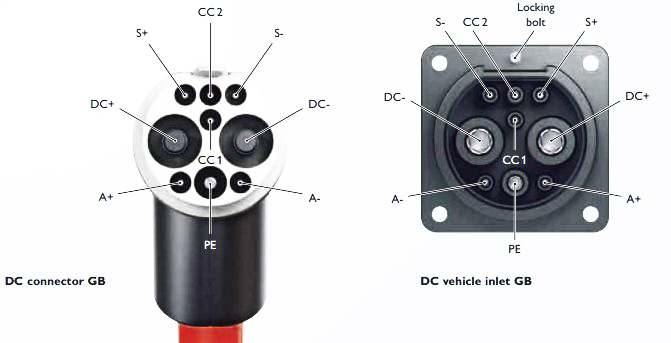
The GB/T 20234.1,2,3-2011 standard has an AC charging connector as shown in Figure 6, a DC charging connector as shown in Figure 7, and a maximum voltage and current and insulation level as shown in Figure 7. GB’s DC charging also uses CAN communication.
| Table 6: AC and DC charging system according to GB standard | ||
|---|---|---|
| Parameter | AC | DC |
| GB standard | ||
| Nominal voltage | Up to 440 V AC | Up to 750 V DC |
| Nominal current | Up to 32 A | Up to 250 A |
| Standard | GB/T Part 2 | GB/T Part 3 |
| IP protection when plugged in | IP55 | IP55 |
| IP protection with protective cap | IP54 | IP54 |
Combined Charging System (CCS) Standard
The Combined Charging System is a quick charging method for battery electric vehicles delivering high-voltage direct current via a special electrical connector derived from the SAE J1772 (IEC Type 1) or IEC Type 2 connector. As the plug is a combination of an AC connector with a DC option the resulting connector is also called Combo Coupler and the variant with Type 2 is abbreviated as Combo2.
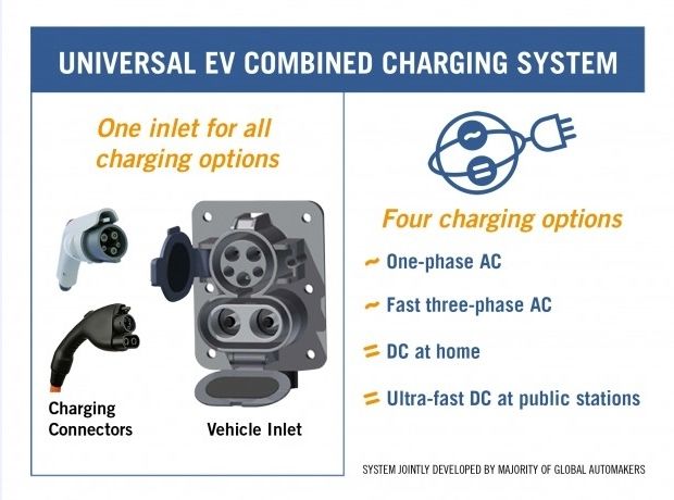
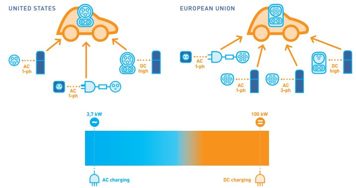
The eight major American and German manufacturers, Ford, GM, Chrysler, Audi, BMW, Mercedes-Benz, Volkswagen and Porsche, released the “Joint Charging System” in 2012. All current charging interfaces are unified so that four modes of single-phase AC charging, fast three-phase AC charging, home DC charging, and super-speed DC charging can be accomplished with one interface.
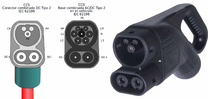
The charging plug of the combined type using the SAE J1772 standard is shown in Figure 8. Figure 9 shows the combined charging plug with charging using IEC 62196 standard. Figure 10 shows the schematic diagram of combined charging and power information.
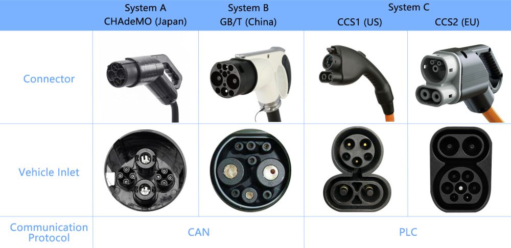
The communication protocol for combined charging uses power carrier communication, PLC (power line communication). While GB/T and CHAdeMO use CAN communication.
Summary
From the above, CCS has both AC and DC charging functions, with strong versatility and high power, but its interface is complex and its compatibility is problematic; GB/T, as China’s national standard, is adapted to local industries, but its international applicability is poor; CHAdeMO is mature in Japan and has outstanding fast charging, but its applicability is poor due to geographical limitations and power constraints; IEC 62196 is highly authoritative and widely applicable, but its standards are complex and updates are delayed; SAE J1772 is the mainstream in North America and is adapted to local vehicles, but it is mainly AC and has low power, and its applicability is narrow internationally. These charging standards each have their own advantages and disadvantages and are adapted to the needs of different scenarios.
The EV charging connector types differ significantly from country to country and region to region. There is still a long way to go to have a unified international standard.


Does anyone have a list of countries and the type of charging station connectors used there ?