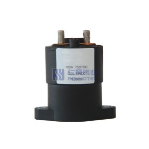
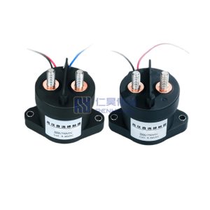
Product Type
| Sealing Type | Ceramic |
||
|---|---|---|---|
| Contact Arrangement | 1H(SPST-NO) |
||
| Power Connection | Inner Threaded Terminal |
||
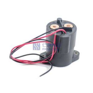
| Coil Connection | Flying Leads |
||
| Sealing Type | Ceramic |
Contact Arrangement | 1H(SPST-NO) |
| Power Connection | Inner Threaded Terminal |
Coil Connection | Flying Leads |
Contact Type
| Contact Material | Silver-plated Copper |
|---|---|
| Contact Material | Silver-plated Copper |
Electrical Characteristics
| Rated Current | |||
|---|---|---|---|
| Rated Voltage | 12-1000V |
||
| Rated Power | 4W |
||
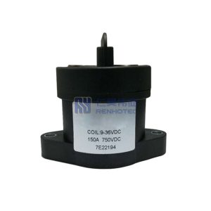
| Coil Voltage | 9-36V DC |
||
| Contact Resistance | ≤1.5MΩ(6V DC/20A) |
||
| Max. Switch Current | 2000A(320V DC) |
||
| Operating Voltage | ≤9V DC |
||
| Release Voltage | ≥3V DC |
||
| Rated Current | Rated Voltage | 12-1000V |
|
| Rated Power | 4W |
Coil Voltage | 9-36V DC |
| Contact Resistance | ≤1.5MΩ(6V DC/20A) |
Max. Switch Current | 2000A(320V DC) |
| Operating Voltage | ≤9V DC |
Release Voltage | ≥3V DC |
Environmental Characteristics
| Operating Temperature | -40℃~85℃ |
|---|---|
| Operating Temperature | -40℃~85℃ |
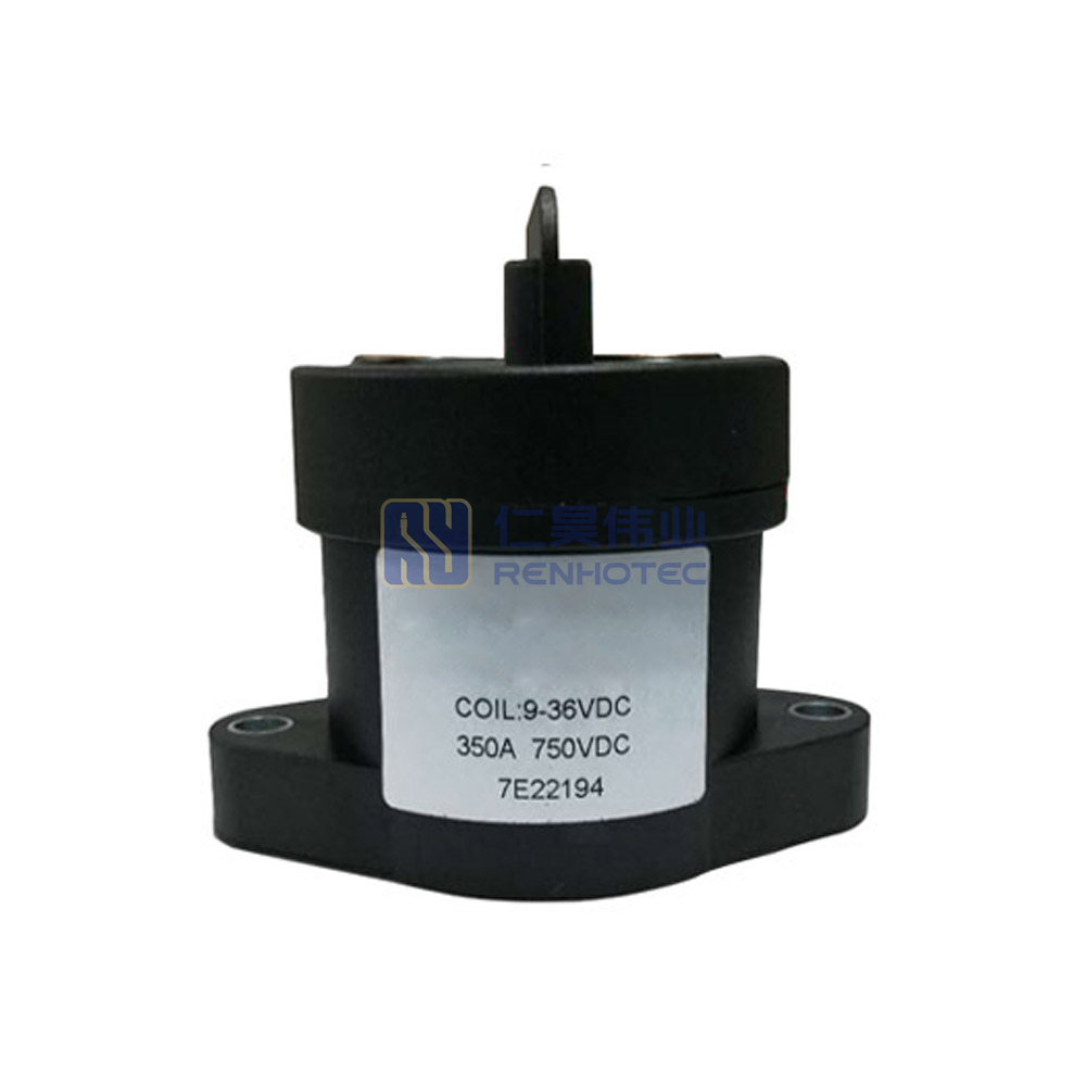
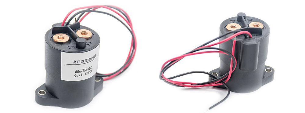
High Voltage DC Contactor
The contacts of high-voltage DC contactors are designed to handle the high current levels of the system without overheating or arcing. They are typically spring-loaded to ensure that they remain in contact during operation and have a large surface area to ensure a low resistance path for the current. The contacts are also designed to be easily replaceable in the event of damage or wear.
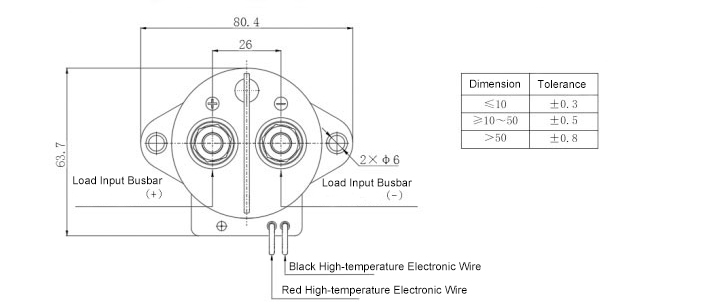
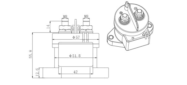
The Wiring Diagram and Installation Hole Bitmap
The Wiring Diagram and Installation Hole Bitmap of the high-voltage DC contactor can be described as follows. The wiring diagram includes the input and output terminals.
Applications
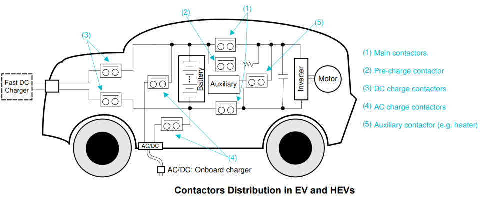
Featuring a magnetic arc blowout design and IP67 sealed, gas-filled chamber. Renhotec High Voltage DC Contactor Relay was developed for the below applications:
Battery Electric Vehicles (BEV)
Hybrid Electric Vehicles (HEV)
DC Charging Station
Energy Storage System

