Introduction
In today’s high-voltage applications, proper connector installation is crucial for system safety and reliability. This comprehensive guide walks you through the professional installation of HVIL (High Voltage Interlock) metal connectors – 12mm right angle single core, ensuring optimal performance and longevity. Whether you’re a seasoned technician or new to HVIL systems, this guide provides the expertise you need.
Understanding HVIL Connectors
HVIL connectors play a critical role in high-voltage systems, particularly in:
- Electric vehicle applications
- Industrial power systems
- Safety interlock circuits
- High-performance electrical equipment
Renhotec’s HVIL connectors feature:
- Superior conductivity
- Enhanced safety features
- IP67 waterproof rating
- Professional-grade materials
- Extended service life
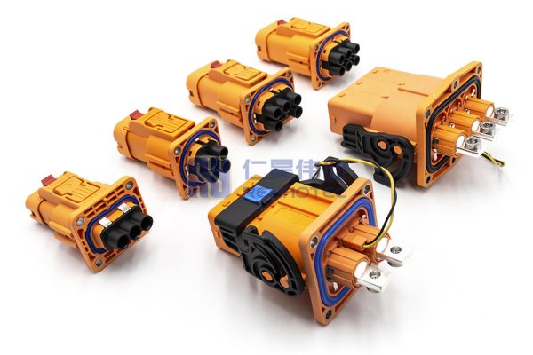
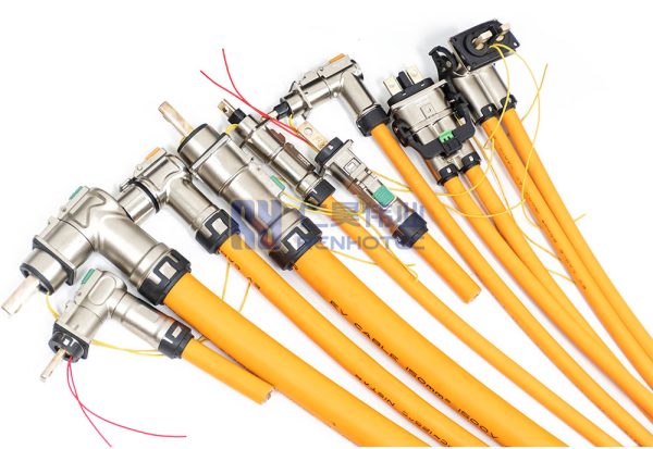
HVIL Connectors Solutions from Renhotec:
Component List
Before beginning assembly, ensure you have all necessary components:
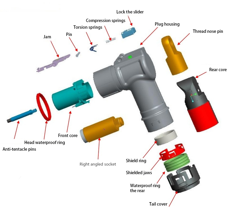
- Locking slider
- Compression spring
- Plug housing
- Latching arm (x2)
- Torsion spring
- Lug pin
- Pin
- Rear grommet
- Front grommet (x2)
- Anti – touch pin
- Head waterproof ring
- Right – angle plug jack
- Shielding ring
- Shielding claw
- Tail waterproof ring
- Tail cover
Professional Assembly Instructions
1. Pre – assembly Preparation
Inspect all components for any damage or defects. Ensure that the surfaces are clean and free of debris.
2. Assemble the Locking Slider and Latching Arm
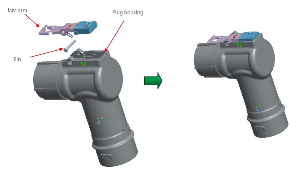
Place the locking slider onto the latching arm according to the correct orientation. Make sure it moves smoothly on the latching arm.
3. Attach the Latching Arm Assembly to the Plug Housing
Position the latching arm with the locking slider onto the plug housing. Align the holes and insert the pin to secure them. The pin should fit snugly to prevent any loose movement.
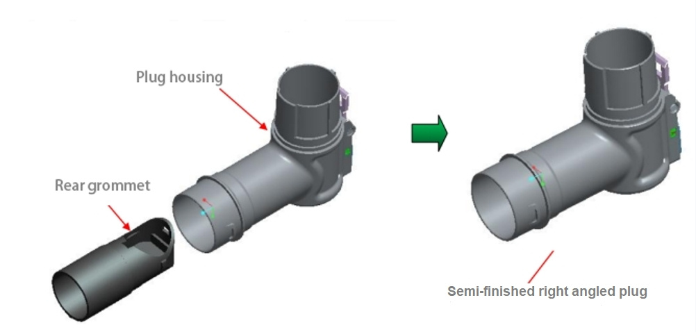
4. Install the Rear Grommet
Take the rear grommet and insert it into the plug housing. Push it gently but firmly until you hear or feel a click, indicating that the grommet and the housing are securely engaged.
5. Prepare the Cable
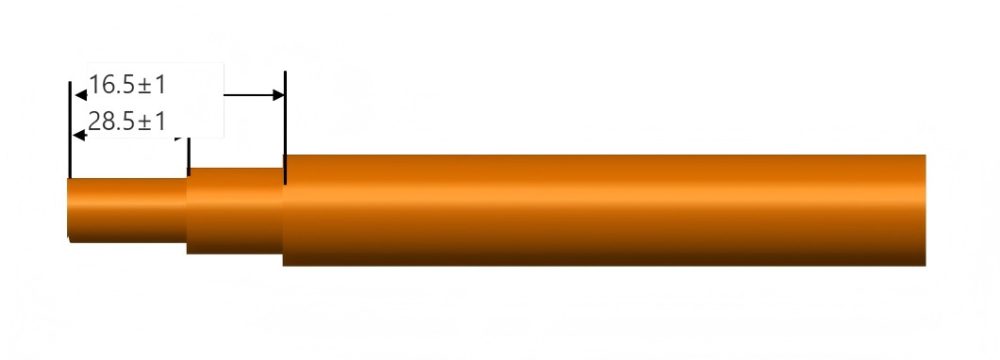
Strip the cable to a length. Be careful not to damage the inner conductors during the stripping process.
6. Assemble the Tail – end Components
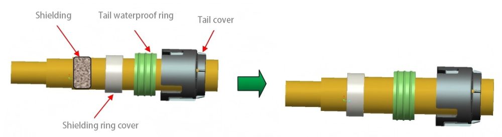
- First, place the tail waterproof ring on the cable.
- Then, slide the shielding ring over the cable and position it on the shielding layer. Crimp the shielding ring onto the shielding layer with a force of 150 – 200 N to ensure a proper connection.
- Finally, attach the tail cover to the cable end.
7. Connect the Lug Pin to the Cable
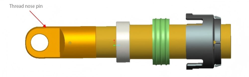
Use a suitable crimping tool to attach the lug pin to the stripped end of the cable. Check the connection to make sure it is tight and the electrical contact is good.
8. Install the Shielding Claw
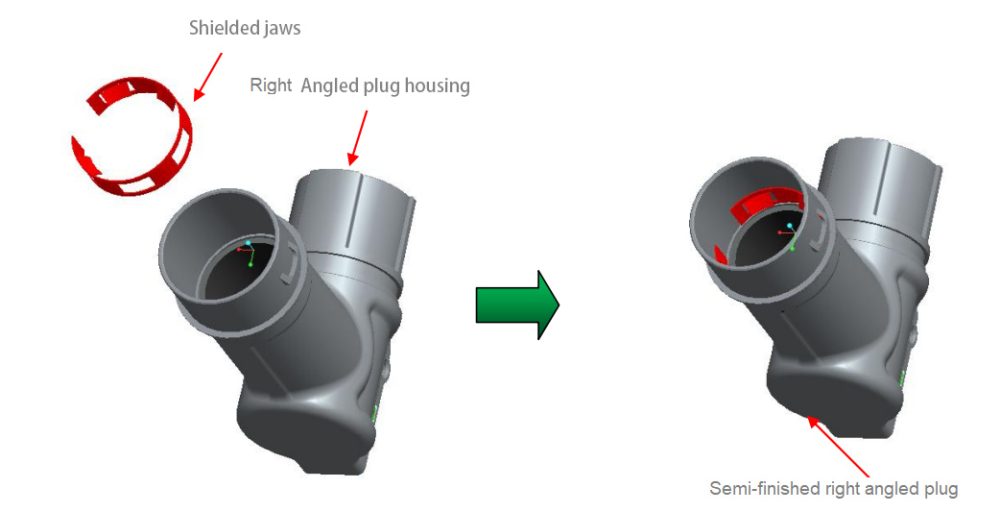
Attach the shielding claw to the right – angle plug housing. Ensure it is properly seated and aligned with the other components.
9. Insert the Cable Assembly into the Plug Housing
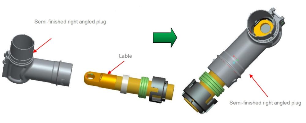
Carefully insert the cable with the attached lug pin, tail – end components, and shielding claw into the plug housing. Make sure the cable is positioned correctly inside the housing.
10. Connect the Right – Angle Plug Jack
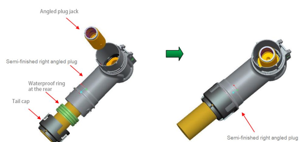
Crimp the right – angle plug jack to the cable and the plug housing. This step requires precision to ensure a reliable connection. After crimping, install the tail waterproof ring and tail cover more securely if necessary.
11. Install the Front Grommet
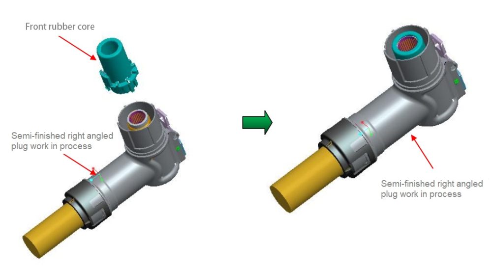
Place the front grommet into the plug housing. Ensure it fits tightly and covers the internal components properly.
12. Install the Anti – touch Pin
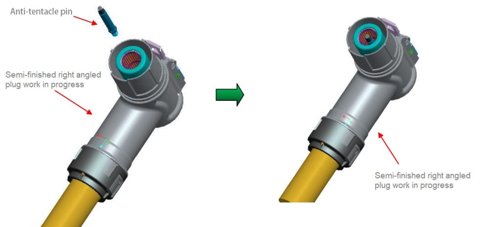
Insert the anti – touch pin into the appropriate position in the front grommet or plug housing. This pin helps prevent accidental contact with live parts.
13. Install the Head Waterproof Ring
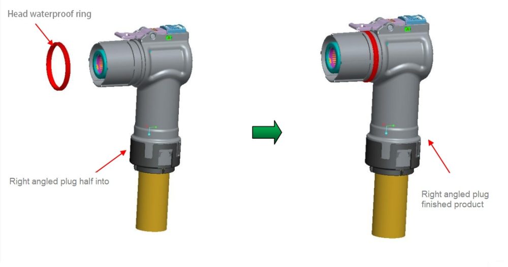
Insert the head waterproof ring into the designated groove on the plug housing. Make sure it is properly seated to provide effective waterproofing.
Mating with the Socket
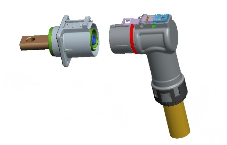
- Select a socket with the same keying position as the right – angle plug.
- Align the pins of the plug with the jacks of the socket carefully.
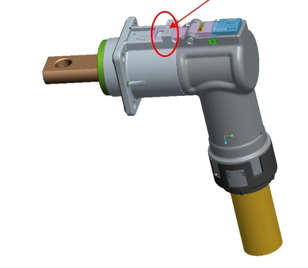
- Push the plug into the socket until the latching arm of the plug engages with the latch of the socket, indicating a successful connection.
Separation from the Socket
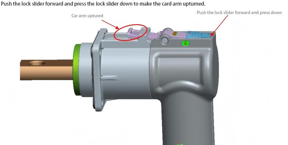
- Push the locking slider forward and simultaneously press it down. This action will cause the latching arm to lift up.
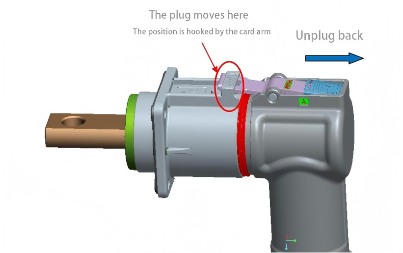
- Pull the plug backward. The front – end reverse buckle of the latching arm will be caught by the socket’s limiting device initially.
- Release the locking slider. The latching arm will fall back. Then, continue pulling the plug backward to completely separate it from the socket.
Inspection and Quality Check
After assembly, mating, and separation, visually inspect the connector for any signs of damage, loose components, or improper alignment. Check the connection between components to ensure they are secure. If any issues are found, disassemble and reassemble the connector as necessary.
Frequently Asked Questions
Q: What tools are required for assembly?
A: Required tools include calibrated crimping tools, cable strippers, and torque wrenches. Renhotec offers a complete toolkit for professional installation.
Q: How often should connectors be inspected?
A: Quarterly inspections are recommended for industrial applications, with more frequent checks in harsh environments.
Q: What is the warranty period for Renhotec connectors?
A: Renhotec offers an industry-leading warranty on all HVIL connectors. Contact our sales for specific terms.
Conclusion
Proper installation of HVIL connectors is crucial for system reliability and safety. By following this comprehensive guide and using premium Renhotec components, you ensure optimal performance and longevity. For more information or to order professional-grade HVIL connectors, visit Renhotec’s HVIL product page.