Definition of Shield Cable
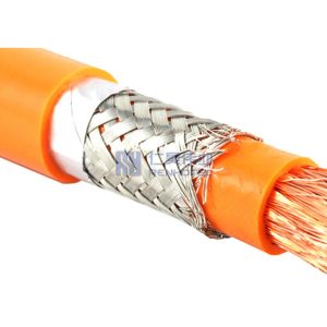
A wire wrapped with a conductor outside the conductor is called a shielded cable. The wrapped conductor is called a shielding layer, which is usually a braided copper mesh or copper foil (aluminum). The shielding layer needs to be grounded, and external interference signals can be guided into the earth by this layer.
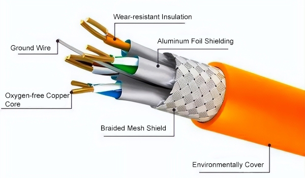
Function of Shielded Cable:
Prevent interference signals from entering the inner layer and conductor interference while reducing the loss of transmission signals.
Structure of Shielded Cable:
1. Ordinary Shielded Cable
Insulation layer + shielding layer + wire
2. Advanced Shielded Cable
Insulation layer + shielding layer + signal wire + shielding layer ground wire
Note: When selecting a shielded wire, the insulation layer of the shielded ground conductor has a conductive function and can be connected to the shielding layer (has a certain resistance).
The principle of shielded cable
The shielded wiring system originated in Europe. It adds a metal shielding layer to the outside of the ordinary unshielded wiring system. It uses the reflection, absorption and skin effect of the metal shielding layer to prevent electromagnetic interference and electromagnetic radiation. The shielding system comprehensively utilizes The balancing principle of the twisted pair and the shielding effect of the shielding layer have very good electromagnetic compatibility (EMC) characteristics.
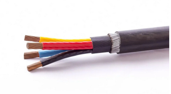
Electromagnetic compatibility (EMC) means that electronic equipment or network systems have a certain ability to resist electromagnetic interference and cannot produce excessive electromagnetic radiation.
That is to say, the equipment or network system is required to be able to work normally in a relatively harsh electromagnetic environment. And at the same time, it cannot radiate excessive electromagnetic waves and interfere with the normal operation of other surrounding equipment and networks.
The main reason why shielded cables resist external interference is that the integrity of signal transmission can be guaranteed to a certain extent through the shielding system. Shielded cabling systems can prevent transmitted data from being affected by external electromagnetic interference and radio frequency interference.
Electromagnetic interference (EMI) is mainly low-frequency interference, and motors, fluorescent lamps and power lines are common sources of electromagnetic interference. Radio frequency interference (RFI) is high-frequency interference, mainly wireless frequency interference, including radio, television broadcasts, radar and other wireless communications.
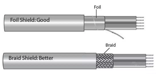
For resisting electromagnetic interference, braided shielding is most effective, that is, metal mesh shielding because of its low critical resistance.
When addressing radio frequency interference, the most effective approach involves a metal foil layer for shielding. This choice is driven by the capability of metal foil to permit the unimpeded passage of high-frequency signals, owing to the gaps in the metal mesh shield.
For mixed interference fields of high and low frequencies, a combined shielding method of metal foil layer and metal mesh should be used, that is, a double-layer shielded cable in the form of S/FTP. This can make the metal mesh shielding suitable for interference in the low frequency range, and the metal foil shielding Suitable for interference in the high frequency range.
Shielded wire connection method
One end of the shielded wire is grounded and the other end is left floating.
When the signal line transmission distance is relatively long, the potential of the two ground points may be different due to the different ground resistance at both ends or the current flowing in the PEN line. At this time, if both ends are grounded, current will flow in the shielding layer, which will interfere with the signal. Therefore, in this case, one point is generally grounded and the other end is suspended in the air to avoid such interference.
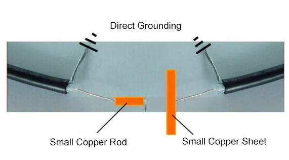
The shielding effect is better when both ends are grounded, but the signal distortion will increase.
The role of shielded wire
The function of the shielded wire is to isolate the electromagnetic field noise source from sensitive equipment and cut off the propagation path of the noise source.
Shielding is divided into active shielding and passive shielding. The purpose of active shielding is to prevent the noise source from radiating outward and to shield the noise source. The purpose of passive shielding is to prevent sensitive equipment from being interfered by noise sources and is a shield for sensitive equipment.
The shielding layer of shielded cables is mainly made of non-magnetic materials. Such as copper and aluminum, and its thickness is very thin, which is much less than the frequency of use of metal materials. The effect of the shielding layer is not mainly caused by the reflection and absorption of the electric field and magnetic field by the metal body itself, but by the grounding of the shielding layer.
Different forms of grounding will directly affect the shielding effect. The grounding methods for electric field and magnetic field shielding layers are different. Can be ungrounded, single-ended grounded or double-ended grounded.
Rated Cable Products

CONTACT US
Renhotec was established in May 2005 and has been specialized in manufacturing and exporting various electronic connectors for over 15 years.
If you have any needs regarding connectors, please contact us via the phone number or email below
Mobile:(+86)18086610187
Email:[email protected]
Related articles:

How EV DC/DC Converters Work and Are Maintained: Are there any potential dangers or risks associated with using aftermarket DC/DC converters in electric vehicles?
The use of aftermarket DC/DC converters in electric vehicles comes with several significant risks and considerations that need to be carefully evaluated:
First, let me explain that DC/DC converters in EVs perform the crucial function of stepping down the high-voltage battery power (typically 400-800V) to the 12V needed for vehicle electronics, lights, and auxiliary systems. This makes their reliable operation absolutely essential for vehicle safety and functionality.
When it comes to aftermarket converters, there are several potential dangers:
Manufacturing Quality and Certification
Aftermarket units may not meet the same rigorous testing and quality control standards as OEM parts
They might lack proper certification for automotive high-voltage applications
Manufacturing variations could affect safety features and protection circuits
Installation and Compatibility Risks
Improper installation could create dangerous high-voltage exposure points
Aftermarket units may not perfectly match your vehicle’s electrical architecture
Integration with vehicle diagnostic and protection systems might be compromised
Operational Risks
Potential for overheating if thermal management isn’t properly designed
Risk of electrical system damage from voltage spikes or inadequate protection
Possible interference with other vehicle systems due to electromagnetic compatibility issues
Maintenance Implications
Vehicle diagnostic systems may not properly recognize or monitor aftermarket units
Special tools or procedures might be required for safe servicing
Documentation and repair procedures may be limited or unavailable